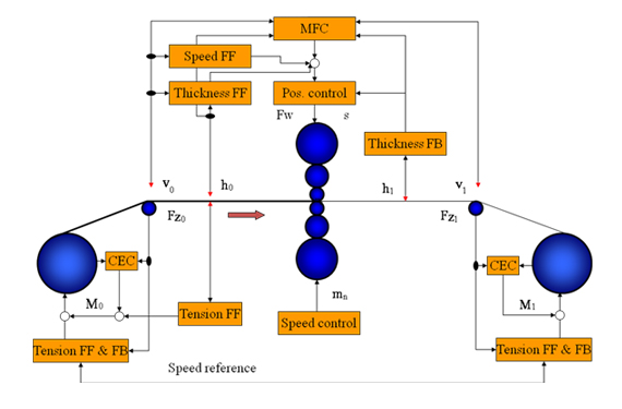
Comprehencive control scheme for the mill (FF:feedforward; FB:feedback;
CEC: coil eccentricity compensation; MFC: mass flow control)
Modes of hydraulic AGC Control
Position control
Roll tilt control
Thickness control
Feedback control
Feedforward control
Dump
Short dump
Calibration or zeroing
Mass flow control
Law of volume constancy
Input volume = Output volume
Hi Vi = Ho Vo
Hi =Entry thickness
Vi = Entry strip speed
Ho = Exit thickness
Vo = Exit strip speed
The delivery thickness: Ho=HiNi/Vo
Gaugemeter working principle
If an absorber is placed in the radiation path, radiated rays are absorbed and
attenuated as they pass through the absorber (material to be measured).
By measuring the residual intensity of the attenuated thickness of the material
can be determinedas
I=I0.e mhp
Where, I0 intensity of radiation without absorber
I is intensity of radiation without absorber
m is attenuation co-effecient
p is the density of absorber and
h is the thickness of the absorber
The attenuation co-efficient determines the measuring range and attainable accuracy
of the thickness measuring and it depends upon the atomic no. of the absorber and
the radiation energy. A schematic diagram for strip thickness measurement with
radionucliodes.

| Sr.No. | Radiation Source | Symbol | Emitted Radiation | Energy Mev | Measuring Al | Range(mm) Fe |
|---|---|---|---|---|---|---|
| 01 | Krypton | Kr85 | Beta | 0.70 | 0-0.40 | 0-0.12 |
| 02 | Strontium | Sr90 | Beta | 2.30 | 0-2.0 | 0-0.70 |
| 03 | Americium 241 | Am241 | Gamma | 0.06 | 2-50 | 0-5 |
| 04 | Caesium137 | Cs137 | Gamma | 0.66 | 2-50 | 4-70 |
| 05 | Cobalt | Co60 | Gamma | 1.17,1.33 | 2-50 | 6-100 |
| 06 | Fluorescent Radiation | Co60 | Gamma | 0.02 | 0-0.2 | 0-0.20 |
| 07 | -------do-------- | Co60 | Gamma | 0.035 | 0.5-20 | 0-1.0 |
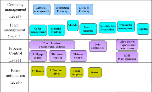
Control Hierarchy